Drawings
What are these and how do I create them?
To begin with, the drawings are the second most important foundation in creating thermal insulation mattresses, after the measurements. Why? Because it is based on these drawings that the material will be cut and, later, the mattress will be created, which is quite a large and complex process.
How are the drawings created?
Technological progress grows stronger every year. And this has also affected the creation of drawings. If previously drawings were created manually*, now “technology will handle it.”
* – some drawings are still created manually. But, as a rule, this is a rare exception rather than “another method.”
Naturally, nothing will happen by itself, so we will have to put in some effort. The Adobe Illustrator program will help us with this. In addition to that, we have mini-scripts that will speed up the process of creating drawings. We will get acquainted with them in the following chapters.
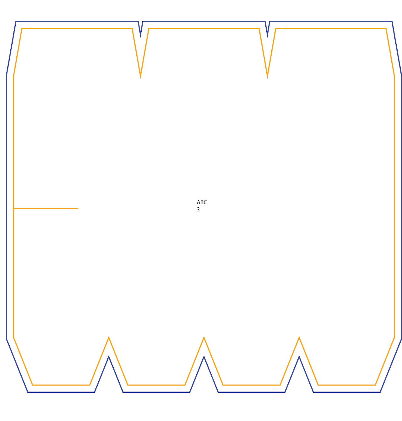
Let’s take a look at one of the drawings as an example.
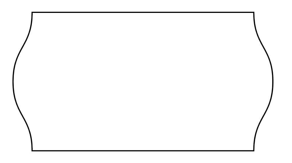
On the image to the right, we can see a drawing that was created using Adobe Illustrator. Here we can see the darts and cutouts, which we will talk
about in the following chapters.
The only thing we need to understand here is that all drawings will have approximately the same appearance.

Creating a Template
Why is this needed?
It’s simple — to speed up the process and avoid repeating this action over and over again. Of course, at the end of this page you will find a link to an archive with a ready-made template for Adobe Illustrator, but it’s necessary to become familiar with the basics.
Where do we begin?
We will follow the images. So, we create a new file, setting the parameters as shown in the image «D-1.1».
Note that we set «Centimeters» in the unit selection field, since the measurements and other values are written in centimeters, which makes it easier for us to transfer the values.
Click the «Create» button and proceed to the workspace.

Image «D-1.1»
File name
Now to the creation. On the right side of the screen, in the “Layers” tab, click the plus icon and create new layers. Double-click the first layer and name it Draw. Then configure the color by clicking the colored square on the right. Set the following values:
Hue: 27; Contrast: 240; Brightness: 120;
Red: 254; Green: 169; Blue: 0.
Save the values and move to the second layer. Perform the same actions, but name the layer Thru-Cut and use the following color settings:
Hue: 160; Contrast: 240; Brightness: 120;
Red: 0; Green: 0; Blue: 254.
The file name is based on the project’s title page. Let’s look at a similar page in the image «D-1.2». We are only interested in the red-marked «fields».
1 – The customer company name
2 – The project name
3 – The mattress material*
We set the file name and review it using the example (image «D-1.3»):

Image «D-1.2»
The first three are the points mentioned above.
What about the rest?
4 – The name of the SIB Duratras location from which the electronic drawings will be created.
5 – The shortened name of the project, which we create ourselves and will use later.
6 – A situational note. If the drawings do not fit on one artboard, a second file will be created, and instead of «Part 1,2,3…» the note «DEEL 1,2,3…» is used.
7 – The file extension of the drawings. By default, Adobe Illustrator saves files in its own format — .ai, and that is the one we need.

Image «D-1.3»

Image «D-1.4»
Enter the file name and save it.
Note that in the image «D-1.4» we did not enter the part and number, but the need for such a note may arise in real work, keep that in mind.
* – in point number 3 in the image «D-1.2», besides the already entered «Sil-Pan», there is also something called «gal». This is, roughly speaking, a designation of which hooks must be used in this project. For the drawings, this information is not needed, so we do not include it.
Layers

Now to the creation. On the right side of the screen, in the «Layers» tab, click the plus icon and create new layers. Double-click the first layer and give it a name — Draw. Then set the color by clicking the colored square on the right. Set the following values:
Hue: 27; Saturation: 240; Brightness: 120;
Red: 254; Green: 169; Blue: 0.
Save the values and move on to the second layer. Repeat the same actions, but name the layer Thru-Cut and set the following color settings:
Hue: 160; Saturation: 240; Brightness: 120;
Red: 0; Green: 0; Blue: 254.

Now let’s move on to creation. On the right side of the screen, in the “Layers” tab, click the plus icon and create new layers. Double-click the first layer and name it – Draw. Next, set the color by clicking the colored square on the right. Set the following values:
Hue: 27; Contrast: 240; Brightness: 120;
Red: 254; Green: 169; Blue: 0.
Save the values and move on to the second layer. Perform the same actions, but name the layer Thru-Cut and set the color settings:
Hue: 160; Contrast: 240; Brightness: 120;
Red: 0; Green: 0; Blue: 254.

Image «D-1.5»

Image «D-1.6»

Image «D-1.7»

Image «D-1.8»
Download the template
As mentioned earlier, we will go over the basics for a general understanding of the work structure and the creation of drawings.
Keep in mind that the file name (the project label) will have to be set anew each time; there is no universal name.
You can download the template archive by clicking the button below this text.
Basics of creating drawings
or how to transfer the measurements into digital form
In addition to looking at how to create drawings, we will also delve into how to read measurement drawings and transfer them onto our canvas in Adobe Illustrator.
In this chapter, we will cover only the basics of creating simple rectangles, ellipses, and their outlines, which will undoubtedly be useful to us later.
Creating a simple drawing
We follow the images.
Image «D-2.1» — what information do we take from here?
1 – The width and height of the mattress.
In the measurements it is written in the format:
width × height
(150 × 40 — on the image «D-2.1»)
2 – The mattress number, which will be written on the mattress itself.
3 – The type of filling. It is not always written, but if something like this appears on the measurement drawing, we write it on the mattress tag.
Some of the filling labels will be covered below.

Image «D-2.1»
Create a rectangle by pressing the hotkey «M» and entering the width and height indicated in the measurements.
Since this is our main layer and not the outline, we check that our rectangle is in the «Draw» layer.
Don’t forget to remove the fill from the object and add a 6 pt stroke.
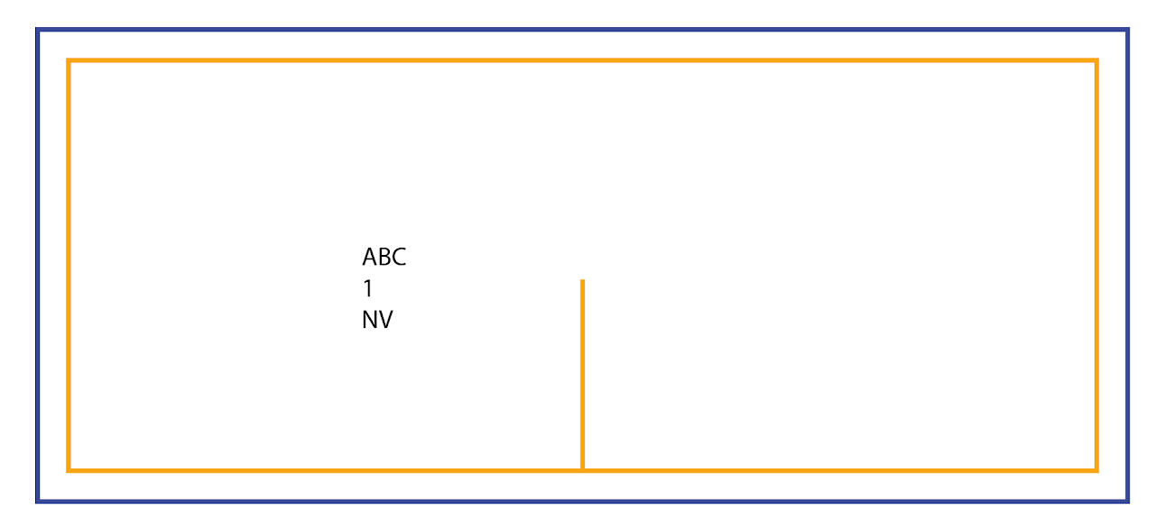
In the image «D-2.3», the rectangle has an orange outline — this is done solely to demonstrate the object’s layer.

Image «D-2.2»

Image «D-2.3»

Image «D-2.5»

Image «D-2.6»

Image «D-2.4»
Select the rectangle and create an offset path for it.
Set the offset based on the material indicated on the title page:
If one of the materials is HT or HTM, then we set the offset to 2 cm. If such material is not present in the project, the offset will be 1.5 cm.
Note that in the image «D-2.6» the outline is blue. This is an important point, because all objects (texts, dd, splits, and so on) will be located in the «Draw» layer, except for the offset paths. All offset paths will be located in the «Thru-cut» layer.
Filling labels
Earlier, we already mentioned the label for the filling thickness. Now we will try to go over the most common types of filling and how they are labeled.
• 50mm – default filling
As a rule, this thickness is not labeled either in the measurements or on our drawings.
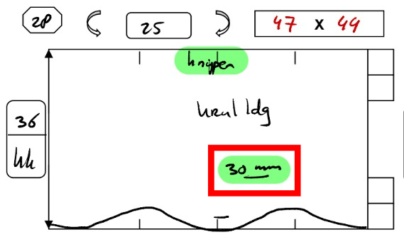
• 30mm – may be written as «30dik» as well as «dun wol»
• 25mm – more commonly appears as «nv»
• 12mm – occurs rarely and is usually labeled simply as «12mm»
Filling «nv»
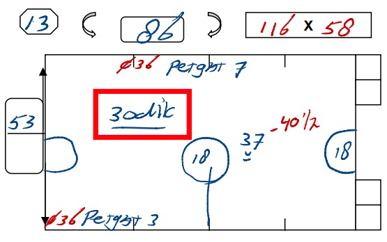
Filling «30dik»
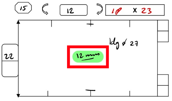
Filling «12mm»
Filling «30mm»
There is also a label such as «DD» / «dd», but it is not enough to simply write it down, since in most cases a separate area is created for it on the drawing. We will cover this size in more detail in another topic.
Symbols on measurement drawings
Different symbols may appear in the measurements, but understanding them is necessary for creating an accurate drawing.
Let’s look at two commonly encountered symbols:

♡ – Middle
A simple indication that a given object, cutout, or other element is located in the center. Often, “middle” means centered along the Y-axis, but of course, there may be measurement drawings where this symbol indicates the center along the X-axis.

⋀ – Direction
In reality, this arrow can point in any of the four directions. If we consider the image mentioned above, it indicates that a margin must be made from the bottom edge of the drawing. In other words, we make the margin starting from the side where the arrow originates.
♡ - Center
A simple indication that a particular object, cutout, or other element is located in the center. Often, the center refers to the Y-axis, but of course, there may be measurement drawings where this symbol marks the center along the X-axis.
⋀ - Direction
In fact, this arrow can point in any of the four directions. If we look specifically at the example shown above, it indicates that you need to make an offset from the bottom edge of the drawing. In other words, the offset is made from the side the arrow originates from.
Scripts & Hotkeys
Why are they useful? Installation
Hotkeys and where to find them
We are talking about the hotkeys built into Adobe Illustrator, their modification and customization “to your needs,” as well as adding new ones.
To open the keyboard shortcuts menu, in an active Adobe Illustrator window press Alt+Shift+Ctrl+K.
Here we create a settings profile and adjust it in a way that is convenient for us.
We recommend assigning a hotkey to the «Measurement» tool, which acts as a kind of ruler. It’s a useful feature for checking your own drawings!

Image «D-3.1»
Operations
We’ve covered the hotkeys for tools.
Let’s move on to operation hotkeys, which will significantly speed up the workflow, making a big step toward automation.
Go to the «Window» tab, scroll down, and find «Actions», then open it.
Click the “plus” icon at the bottom of the panel and create a new action.
Choose the color, name, and key at your discretion.
After creating the action, recording will start immediately. Stop it by clicking the “square” at the bottom of the Actions window if your materials for recording are not ready.
Create the objects we need. In our example — the mattress and the darts.
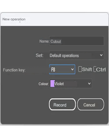
Image «D-3.4»

Image «D-3.5»
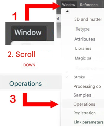
Image «D-3.2»
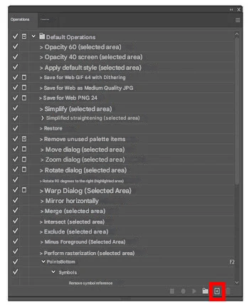
Image «D-3.3»
Start recording by clicking the “circle” at the bottom of the Actions window.
Select the objects and cut them.
Stop the recording and note that an action has been added to our operation.
Now, when you press the previously chosen key (or key combination), your action will be triggered, which can save you time and speed up the drawing creation process.

Image «D-3.8»
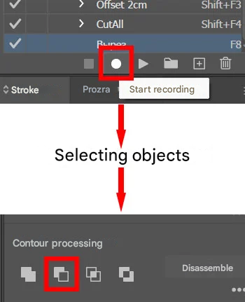
Image «D-3.6»

Image «D-3.7»
In this way, we can create an action for almost any operation (or even a chain of operations) that does not have its own hotkey.
You can create adding a 1.5 cm or 2 cm offset path; cutouts of the upper or lower horizontal edge; moving objects to another layer, and so on.
We have prepared an archive with ready-made actions. You can learn how to install them and what actions are included by clicking the button below this text.
Scripts
If actions allow us to replace several steps with a single one, then scripts will add an additional menu that lets you quickly create PET objects and mattress bases with darts, which without this panel could take several minutes to create.
User guide
Mattress creation menu

Image «D-3.9»

Let’s go in order, looking at the image «D-3.9».
First, we see the items responsible for the upper and lower darts.

First, we see the checkboxes responsible for the presence of darts, with separate sub-options for the upper and lower ones (if the checkbox is not enabled, for example for the upper darts, then they will not appear in the final result).
Type of darts > quantity and a checkbox that is responsible for splitting one krimp into two parts and placing them on the sides.
We examined this type of split in more detail in the topic about darts.

Next is the mattress creation panel. The width, height, and the checkbox that is responsible for creating the mattress base itself.

If it is disabled, then when creating darts they will simply be placed according to the required width and height (if both horizontal pairs are created).
The «Create» and «Cancel» buttons are responsible for creating the object and closing the script creation window.

PET creation menu

Image «D-3.10»
Looking at the image «D-3.10».
Diameter of the PET (in cm) and the type.

By selecting the «PET Gat» type, we will see an additional panel where we specify the size of the Gat.
Select the outline size and create it.
Installing scripts
The installation instructions and the link to the script archive are available via the button below this text.
Krimps
Formula and Creation
What are krimps?
If we speak in simple terms, krimps are ordinary triangles that we will later cut out of the main object — the mattress drawing.
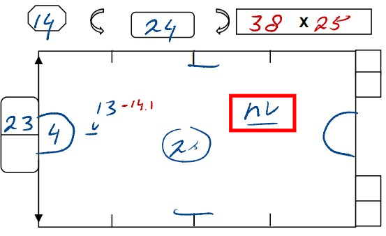
In the images «D-4.1» – «D-4.3» you can see measurement drawings where, on the right, in the area marked with small red squares, the size of the krimp is written. This size will be applied to the side on which it is indicated.

Image «D-4.1»

Image «D-4.2»

Image «D-4.3»
How and where are krimps placed?
As a rule, there are 4 krimps by default, and they are usually placed on the horizontal edges of the drawing.

Image «D-4.4»
Krimps are placed as follows: two side krimps are positioned with their centers aligned exactly to the vertical edge. As a result, we split two krimps in half, getting halves of 0.5 and 0.5, which together give 1 — meaning 1 full krimp.
The remaining three krimps are placed as follows: two at the quarter positions and one in the center.
This gives us a total of 4 krimps.
(Image «D-4.4»)
Krimp Creation and Formula
To create krimps on a mattress, we need to open the script menu.
Here we enable the checkboxes depending on which krimps we need: upper or lower.
When creating “regular” krimps on a “regular” mattress, we simply set the size (type), the quantity, and do not touch the checkbox «Split 1 krimp into 2 parts», which we will talk about a bit later.

Image «D-4.5»
Krimps Formula
So, we focus on the drawing and look at the measurements marked with numbers (image «D-4.5»).
The first thing we need is the calculated mattress length (1), then we look at the raw circumference of the narrow side (2).
We begin calculating:
from the calculated length we subtract the raw circumference of the narrow side, and then subtract an additional 8 cm.
It turns out: 116 − 61 − 8 = 47
But since the krimp size is always an even number, we round the result up when necessary, so the final result is m48.

Image «D-4.6»
Calculated mattress length − circumference of the narrow side − 8 cm = krimp size (+rounding up to the next even number if the result is odd).
Exceptions to the krimp placement rule
Of course, like any other rule, ours has exceptions. For example, krimps in the case of side “waves” on a mattress. Let’s look at such a case below.
Krimps with side waves

Image «D-4.7»
Such krimps are placed as follows: along the short side of the mattress, the krimps are positioned without splitting one of them into two parts, as is usually done. This means all our objects will be located inside, and none of them will be on the vertical edge.

Image «D-4.8»
I think you already understood that to achieve this result in the mattress-base creation script menu, you simply need to uncheck the option «Split 1 krimp into 2 parts» and enter the length of the short side in the «Width» field.
Cutouts & Splits
What is this? Formulas and specifics
What is it?
Splits are, roughly speaking, thin cutouts on mattresses that will be sewn together. For example, we have krimps, and we have splits. A split is the same as a krimp, but it is not cut across the width — only along the length.
Cutouts are often circles but can also be rectangular. The cutout is made on the main mattress object.
Splits
In the images «D-5.1» and «D-5.2» you can see what splits look like on a measurement drawing.
On the drawing «D-5.1» the split is placed directly on the “wave,” and it was calculated along the short side (kk), which we discussed in the article about “waves.”
For us (and generally in the process of creating the drawing), a split can simply be called a straight line, because one way or another, we will depict them as straight lines on the drawings.
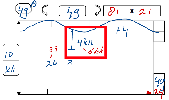
Image «D-5.1»
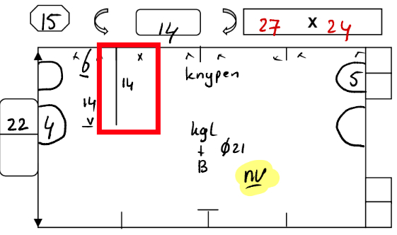
Image «D-5.2»
Examples of splits
The colors are used for a visual example to show which layer the object is in. In a real project, all objects will be black.
Splits Formula
The formula is needed to calculate the offset or the length of the split. It is quite simple:
From the calculated height of the mattress, we subtract the uncalculated height and divide the result by 2.
From the calculated height of the mattress, we subtract the uncalculated height and divide the result by 2.
Looking at the image «D-5.3», we see:
From the calculated 29 cm height, 27 cm uncalculated were subtracted and divided by 2 = the increase amounted to 1 cm.
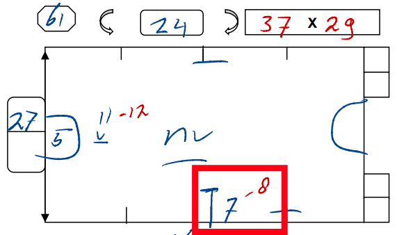
Image «D-5.3»
Cutouts
There can be very, very many types of cutouts, so we will look only at the most commonly encountered ones.

Image «D-5.4»

Image «D-5.5»

Image «D-5.6»
Let’s start with simple cutouts. Circular cutouts on vertical edges are common. Similar cutouts of rectangular shape are also not rare, and they are created using exactly the same principle.
To create such cutouts, you need to align the required object (the future cutout) by its center to the vertical edge and cut it out.

Image «D-5.7»

Image «D-5.8»

Image «D-5.9»
Sometimes cutouts may intersect with krimps. In such cases, we move the object that will be used to create the cutout inward, so that the vertical vertex (or the center of the vertical edge), depending on the cutout’s position, intersects with the edge created by the krimp (images «D-5.7» – «D-5.9»).
If the cutout “eats into” the lower krimp, then the lower point or the lower edge must intersect with the contour created after cutting the krimp. But if the cutout “eats into” the upper krimp, then the upper point or edge must intersect with the contour created after cutting the krimp.
Cutouts Formula
If there is a cutout without a diameter and only a mattress number is indicated (image «D-5.10»), we need to calculate it.
The formula is as follows:
The width of the specified mattress / the number π;
Using the example from images «D-5.10» – «D-5.13»:
31 / 3.14 = 9.8… = 10 cm
In this case, 9.8 was rounded up to 10

Image «D-5.10»

Image «D-5.11»

Image «D-5.12»
Cutouts with splits

Image «D-5.13»
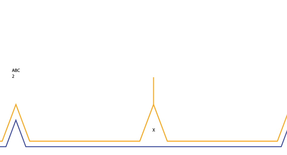
Let’s look at another type of cutout — cutouts with splits. Essentially, these are the same cutouts, but they are not located on the vertical edges; instead, they are inside the mattress itself. And here, the split acts as a “bridge,” connecting the cutout to the edge of the mattress.
If a split with a cutout (or without one) is “placed” on a krimp, then the contour of that krimp is closed and marked with the symbol «X».
Note that in cases where the split is “placed” on a straight edge of the mattress, the «X» symbol is not placed under the split.
Image «D-5.14»

Image «D-5.15»
Cutouts on horizontal edges

Image «D-5.16»

Image «D-5.17»

Image «D-5.18»
Such cutouts often “sit” on krimps, and we need to split them into two parts. To divide such a cutout evenly, we place the cutout with its center aligned to the edge of the krimp.
Looking at the drawing (image «D-5.16»), we can see what offset is needed from the mattress edge to the edge of the cutout.
The formula (if it can be called that) is simple — we take the diameter of the cutout, divide it in half, and subtract the offset length from the result.
Using the example:
the circle diameter (a) / 2 − the offset (b) = the object offset (c).
11 / 2 – 4 = 1,5 cm
Using the point-creation tool, we create new points on the cutout at the intersections of the object boundaries (hotkey +), then delete the ones we don’t need. We place the «X» symbol inside the cutout, duplicate it to the opposite side of the krimp, and create the outline for the entire mattress.
Note — we do not close the contour to this krimp with the «X» symbol, as happens, for example, with splits. And we also do not cut out the circle; we only leave the «X» inside.

Waves
Types of “waves”
“Waves” can be divided into two types: vertical and horizontal. They require special attention because a mattress may have a wave at the bottom while still “facing” in different directions.
What is the difference between these types?
If we do not consider their position, the difference lies in whether they are mirrored on the opposite side. Horizontal waves do not always have a mirrored version, whereas vertical waves almost always — in 99% of cases — are mirrored and have a “twin” on the opposite side.
Horizontal waves
Horizontal waves also come in two types: internal and external. How to tell them apart?
Look at the images «D-6.1» – «D-6.4» — pay attention to where the central curve is “facing.” If the wave is directed “away from the mattress,” it is an internal wave; if it is directed inward, then it is an external wave.
It may sound confusing, but you will clearly see the difference later when we begin creating such waves.
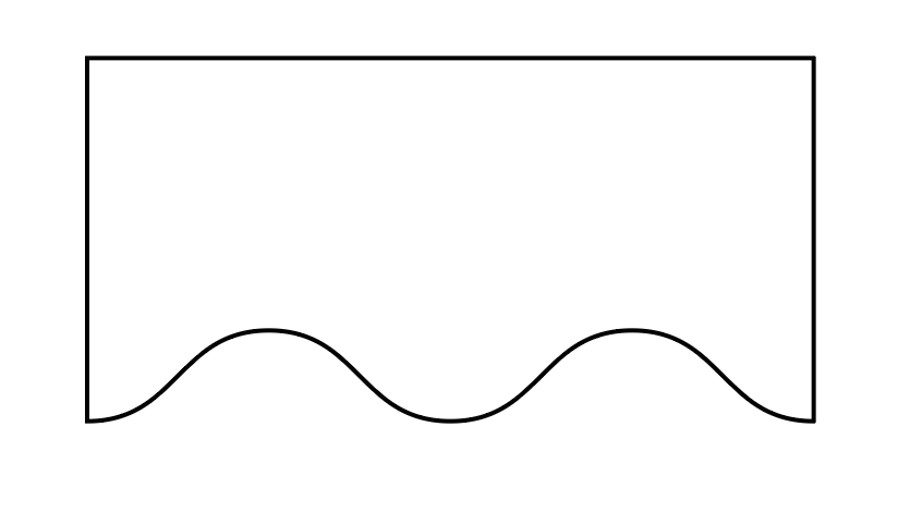
Image «D-6.1»
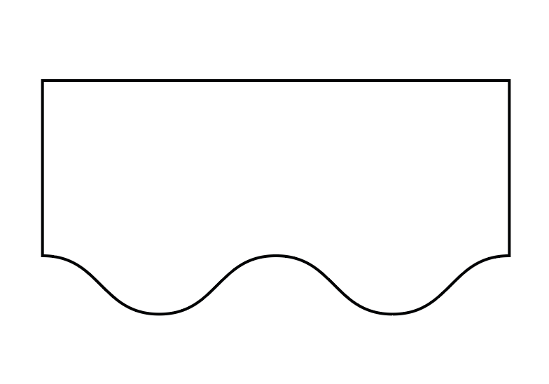
Image «D-6.2»
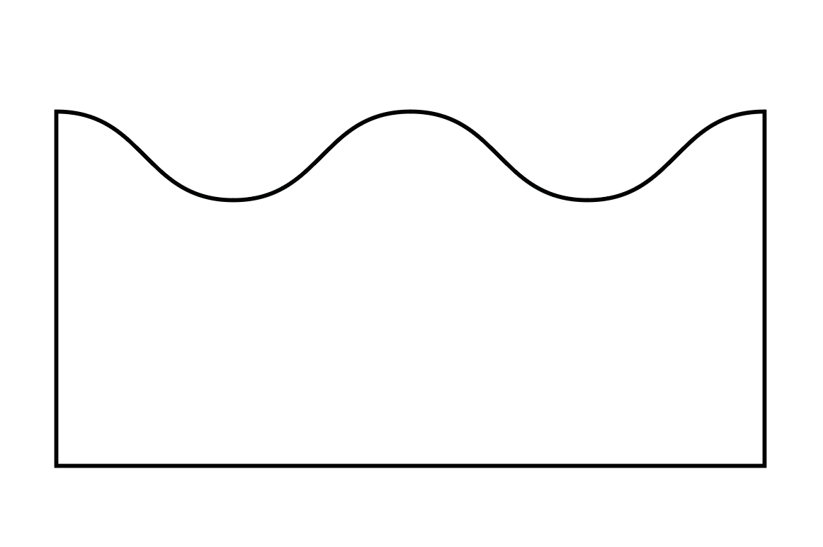
Image «D-6.3»
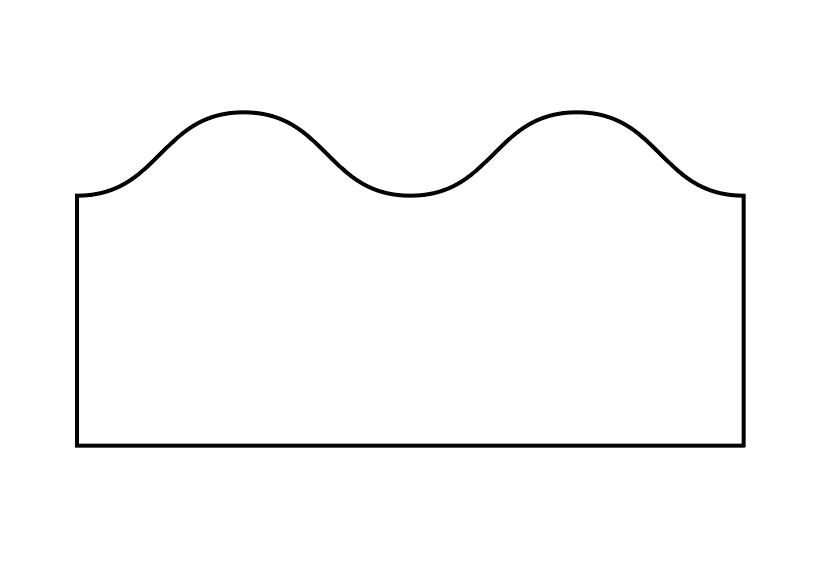
Image «D-6.4»
Formula for horizontal waves
Using the example in image «D-6.5», we see that the wave is not calculated.
In that case, we look at the calculated height and subtract the uncalculated height from it. Then we subtract the filling increase, and, if present, we subtract the krimp increase (in our example there are none). The krimp increase is always 3 cm.

Image «D-6.5»
The formula looks as follows:
Calculated height − uncalculated height − filling ( −3 cm for krimps, if present ) = wave height in cm.
Using the example:
29 − 22 − 2.5 = 4.5 = 5 (rounding)
Creating external horizontal waves
Image «D-6.5»
For the example, we will use the same drawing (image «D-6.5») that we showed earlier when demonstrating how to calculate the wave height.
First, we look at the drawing and determine the type of horizontal wave. In our case, it is external.
This means that, for convenience, we create the rectangle (the mattress base) immediately subtracting the wave size from the height: 29 − 5 = 24.
If the wave were internal rather than external, we would not need to subtract the wave height from the mattress height.
Creating the base of the wave
Of course, remember the hotkey **/** — we create a straight line exactly along the edge of the required side.

Place the base in the required position
We divide the wave height in half and get the required value. If the wave is at the bottom — then for an external wave we add **+**, and if it is at the top — we subtract **−**. We add or subtract half of the wave height from the Y-axis position.


We move on, and now in the top panel we select the “Effect” tab, then “Distort & Transform” ➔ “Zig Zag”.
In the panel that appears, we set the following settings:
Size: the wave height divided in half — 2.5 cm. Ridges: looking at the drawing, we see there are three, so we set the same value — 3. Points: must be set to Smooth.

Select the wave object and go to: “Object” > “Expand Appearance”.

Select the object and click “Join.”

We get a single object with a wave.
Additional note on external waves
If the cutting function did not work, we do it manually.
Using the “A” cursor, we delete the edge of the main object and connect the outer points on both sides one by one, selecting them beforehand.
If necessary, zoom in closer to the connection area and manually correct any incorrect joining (remember that with the Ctrl+J key combination we can join points).
Fixing incorrect wave-to-base connections in the drawing
Creating internal horizontal waves
Essentially, the principle is the same, but with the offset applied in the opposite direction — meaning inside the rectangle:
create a straight line, then along the Y-axis apply a + offset (if it’s the top wave) or a − offset (if it’s the bottom wave) equal to half of the total wave height.

Then everything is the same as before: Effect > Zig Zag > Half of the total height > Required number of ridges > Smooth points.
After that, don’t forget: Object > Expand Appearance.
And that’s the entire difference between creating internal and external waves?
Not quite. If you remember, when creating an external wave, we merged two objects.
An internal wave, however, must be cut out, similar to how we cut out krimps, for example.
And those who have set up additional hotkeys with actions can simply select both objects and press F2.

And yes, as you may notice, we can align the internal wave to the bottom line, which allows us to avoid cutting the bottom edge of the object manually.
What are kk and Lk?
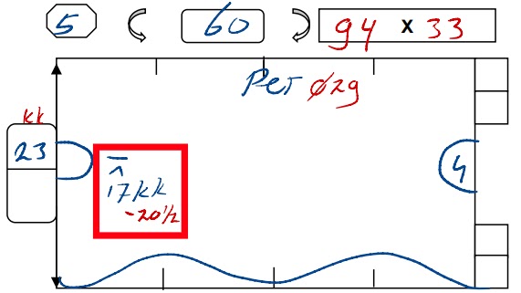
Image «D-6.17»
It is not uncommon to see kk (and sometimes Lk) on mattresses with waves. What is it?
This note indicates from which side of the wave we need to make the offset.
More precisely, kk means an offset from the short side, and Lk means an offset from the long side.
In image «D-6.17», we see the calculated 20.5 kk, which means that we will offset 20.5 cm from the short side.
Which side is the short one and which is the long one?

Image «D-6.18»
Looking at the image «D-6.18»: the orange circle marks the Lk — the points farthest from the center.
The green circle marks the kk — the points that are closer to the center.
We align the object by its center point to the required one (kk or Lk) and make the offset indicated in the drawing.
Vertical waves
In 99% of cases, such waves are identical in their creation principle; they are all external (if we use the terminology from the section on horizontal waves).
As mentioned earlier, they are often mirrored and have a twin on the opposite side.
And, as a rule, they have only one curve. Naturally, if the project and measurements require it, this number may be different.
Formula for vertical waves

Image «D-6.20»
The principle is even slightly simpler than with horizontal waves.
In image «D-6.20» the necessary data for calculating the wave height is marked.
We take the total width 1 (130) and subtract from it the short width 2 (116):
130 − 116 = 14
The result is the combined height of both waves. But we need just one wave:
14 / 2 = 7 / 3.5
So: 7 cm is the height of one wave, and 3.5 cm is its half, which we need for the wave creation panel and for the offset from the outer edge of the base.
How to create vertical waves?

The principle is exactly the same as with horizontal waves:
Create a straight line along one of the vertical edges ➔ apply a + or − offset, but now along the X-axis ➔ add a zigzag, but with 1 ridge (or as many as the project requires) ➔ expand appearance ➔ join — done!
As already mentioned several times: vertical waves have their mirrored version.
Therefore, after you create the first wave and expand its appearance, drag this wave to the opposite vertical edge.
Then reflect the second wave horizontally by pressing the button responsible for this function (found in the Properties panel near the coordinates and size).


And yes, if the connection turns out incorrect, you will have to fix it manually, the same way as with external horizontal waves.
DD
and additional sized
What is this?
Essentially, DD and insert dimensions are the same thing, but since DD appears much more often, we will focus on it. Just keep in mind that the construction principle is identical.
Briefly put, DD is an area inside the mattress that will not be filled with any insulation, unlike insert dimensions. But the construction principle for the drawings is identical.
Looking at image «D-7.1», we see that DD, just like the main part of the drawing, is located in the Draw layer.
We also note that DD can vary in form, but the creation principles are almost the same.
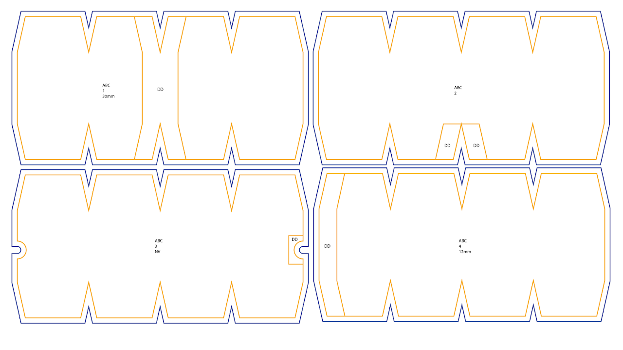
Image «D-7.1»
Creating DD

Image «D-7.2»

Image «D-7.3»

Image «D-7.4»
Let’s look at the drawing in image «D-7.2». We create the mattress base. What next? How do we add DD?
First of all, let’s return to the drawing — what is written next to DD? Nothing, correct. And that means the width will be 10 cm, and the height, as we can see, is the full mattress height, which is 40 cm.
We create a rectangle 10×40.
In the drawing, DD is located in the center (at least no shifts are indicated), so we place it in the center. For convenience, we will create straight lines (hotkey /). We create a straight line from the vertex of the central krimp to the opposite side and place the DD base centered on it.
Next, after removing the center guide, from the krimp vertex we pull another straight line, but this time horizontally, so that it intersects the DD base.
After that, using the tool for creating new anchor points (hotkey +), we create two points on the sides of the DD base (on both sides, and also don’t forget the top part, because as we can see, there is also a krimp there).

Image «D-7.5»

Image «D-7.6»

Image «D-7.7»

Image «D-7.8»

Image «D-7.9»

Image «D-7.10»
We take one of the points and drag it to the outer krimp point. Then, by selecting the DD base point, in the properties panel along the X-axis we set a + or − offset (if it’s the left side, we offset backwards with “−”; if it’s the right side and the offset goes to the right, then “+”) from that point.
The required offset is obtained by dividing the full DD width in half: 10 / 2 = 5 cm
After doing this on both sides, and also on the top — we use the A cursor to select the vertical edge of the DD base and delete it with the Delete key.
Don’t forget to write “DD” (or “dd”, whichever you prefer) inside, and that’s it — we can create the outline and label the drawing.
Additional note
It should be understood that the example above is just an example. Yes, most DD areas are created this way, changing only the DD width and the point offsets from the krimps (if they are needed at all). But that’s not all. Naturally, there are different kinds of DD, but the principle of creating them is similar.
Looking at the drawing in image «D-7.10», we see a DD, but it differs from what we saw earlier.
However, the principle is the same: 2 cm on the left and 2 cm on the right, but in this case everything fits within one krimp in height, instead of extending beyond it.
In the third image, we see a DD that is different from the previous ones. But again — bring it in place, trim it, add the “DD” label, and it’s done.

Image «D-7.11»

Image «D-7.12»

Image «D-7.13»
PET’s
What is PET?
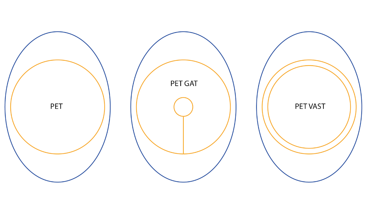
Image «D-8.1»
If we don’t go into specific terminology, PETs are generally mattresses in the shape of a circle, which are not considered separate mattresses but serve as an addition to the main one. Naturally, there are exceptions — for example, PETs that are not circular but have a more rectangular shape. One way or another, for now we will look only at the main types of PETs.
We have three main types:
Regular PET, PET GAT, and PET VAST
In the images «D-8.2» – «D-8.4» you can see how the requirement to create a PET for a specific mattress is indicated.
⌀ 29 — diameter 29 cm in image «D-8.2»;
⌀ 36 — diameter 36 cm in image «D-8.3», but what are 7 and 3?
If you look at the image above, you’ll see that the PET with the codename GAT has another cutout inside it, from which a split goes to the main layer of the PET. Those 7 cm and 3 cm are the diameters of that internal cutout.
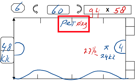
Image «D-8.2»
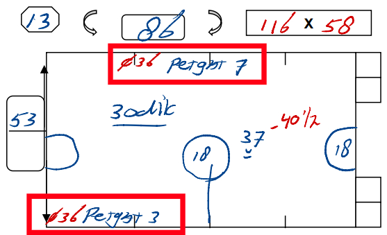
Image «D-8.3»

Image «D-8.4»
⌀ 21 — diameter 21 cm in image «D-8.4». But what is this mysterious Vast? Everything is simpler than with PET-GAT. From the main layer, we create another one with an offset of 1.5 cm. This second layer is not considered a contour, and therefore it is located in the main orange layer — Draw.
Also, PET Vast is the only PET whose presence will appear on the main drawing. How? Pay attention to which side indicates that a PET Vast must be created for the mattress — on that side, 2 cm will be added to the height and a DD will be inserted. We will cover this in more detail during the creation process.
Creating PETs
We will look at two ways of creating PETs: manually, using Adobe Illustrator’s built-in tools, and using the add-ons created specifically for S.I.B. Duratras.
Regular PET

Image «D-8.5»

Image «D-8.6»

Image «D-8.7»

Image «D-8.8»
To begin, we will create a PET manually using Adobe Illustrator’s tools. Let’s look at the drawing in image «D-8.5» as an example.
We will not create the entire mattress, since we are focusing only on PET creation.
So, manual creation. First, using the L hotkey, we create an ellipse and enter the dimensions shown in the drawing.
On the created ellipse, we add an offset path with the required value: 1.5 cm or 2 cm. We add +6 cm to the height of the offset path.
Remember to check the layers: everything except the contour goes into the Draw layer, and the contour goes into the Thru-cut layer.
We set the text inside to match the main mattress. The number is exactly the same (in our example, the mattress and the PET both have number 26).
To create a regular PET using the script menu, we first open it.
We enter the required diameter (in our example — 29 cm).
We leave the PET type as Default, and we choose the contour depending on the project material (or a specific mattress, if the measurements require it).
We click Create and get a ready PET. The objects are already placed into the correct layers (the color is added only for demonstration; in reality everything will be black, just placed in the correct layers).

Image «D-8.9»

Image «D-8.10»
PET Gat
Let’s examine the next PET type — PET Gat. As we mentioned earlier, this is a PET that contains an internal cutout with a split.
How do we create it? We will use the measurements in image «D-8.11» as an example. As you can see, the main diameter is written separately from the Gat value — this is normal practice.
We create an ellipse (hotkey L) with a diameter of 23 cm. Then we create another ellipse, but this time with a diameter of 5 cm, and we place it center-to-center inside the main ellipse.
Using a straight line (hotkey /), we draw from the bottom anchor point of the inner ellipse to the bottom anchor point of the main ellipse. Remember that all these objects remain in the Draw layer.
We add an offset path: 1.5 cm or 2 cm. To the offset path we also add +6 cm of height in the object’s properties.
We set the label and place it above the inner cutout.

Image «D-8.11»

Image «D-8.12»

Image «D-8.13»

Image «D-8.14»

Image «D-8.15»

Image «D-8.16»

Image «D-8.17»

Image «D-8.18»
To create it through the script menu, we open it and enter the required diameter.
We select the PET type as PET Gat. In the window that appears, we enter the diameter of the Gat.
We choose the contour size depending on the material.
We press the Create button. All objects are automatically placed into the correct layers.
We set the PET name the same as the mattress.
PET Vast

Image «D-8.19»
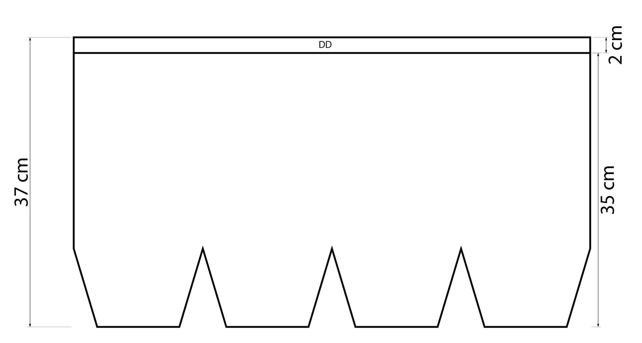
Image «D-8.20»
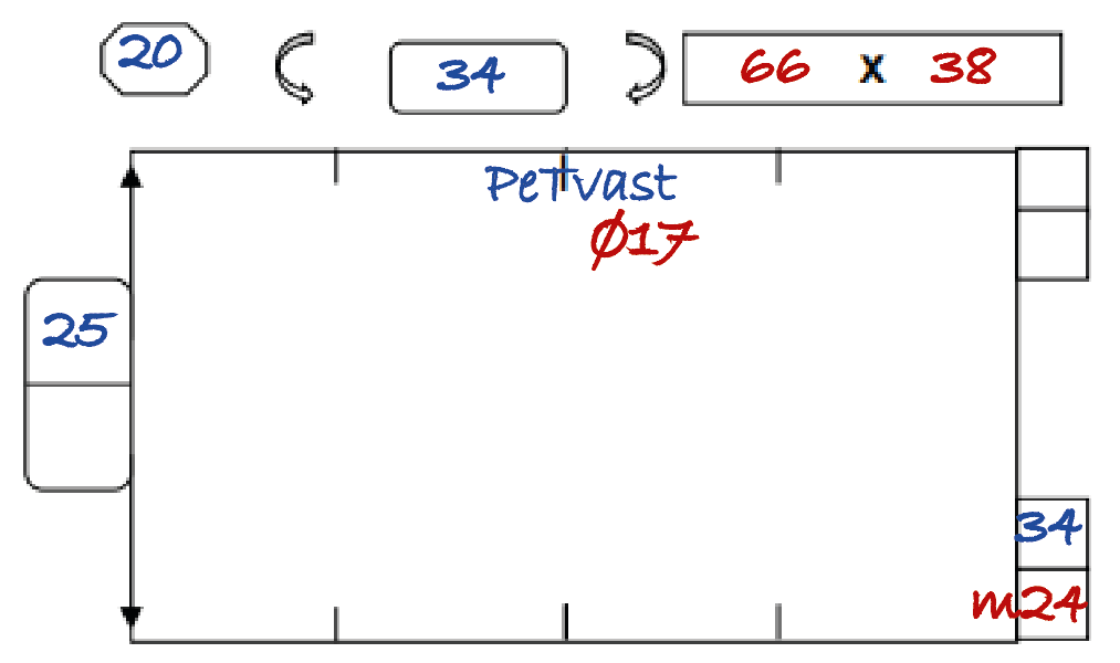
Image «D-8.21»

Image «D-8.22»
The last of the main PET types. How do we create it?
Looking at the drawing in image «D-8.19». First, pay attention to the measurements, specifically the height. If it says «ex», then we need to add +2 cm to the height, and on the side where the note about PET Vast is written, we must offset 2 cm inside the mattress by creating a straight line along the full length and placing the “DD” label inside.
If “ex” is not written, but PET Vast is present, we still add +2 cm to the respective side (image «D-8.21»).
Let’s return to the PET. We will create a PET using the drawing in image «D-8.19» as an example.
We create an ellipse with the specified diameter. Now we create a contour with a 1.5 cm offset, but we leave this contour in the Draw layer.
Next, we create another contour with an offset of 1.5 cm or 2 cm, depending on the material type. This contour is moved to the Thru-cut layer, and we also add +6 cm to its height.
We assign the PET the same name as the mattress.

Image «D-8.23»

Image «D-8.24»

Image «D-8.25»

Image «D-8.26»

Image «D-8.27»

Image «D-8.28»
To create a PET Vast through the script menu, we first open the menu itself. In the PET size field, we enter the values given in the measurements.
We select the PET type as PET Vast.
We click Create and get the PET we need.
The objects will automatically be distributed into the correct layers. All that remains is to apply the name — the same as the mattress.
Non-standard PETs
Sometimes you will encounter PETs in drawings that differ from the standard types. Listing all of them is simply impossible, since such PETs are created according to the specific needs of the client’s project. However, we will still try to show examples of such PETs.
These PETs cannot be created through the script menu, as they fall into the category of standalone objects that can only be created using the built-in tools of Adobe Illustrator.

Measurement drawing of a non-standard PET
Note that this type of PET was given its own number, which means the number will not match the number of the main mattress for which this PET is created.
However, you may also encounter non-standard PETs that do have the same number and name as the main mattress.

The non-standard PET drawing created in AI
The non-standard PET drawing created in AI
As you can see, no +6 cm height is added to the contour, because the shape of the object itself does not require it.
The shape also has rounded corners. The radius of the rounding may be specified in the measurement drawing. If not, ask your measurement colleagues for clarification.
Bochten
Creation and nuances
What is a Bocht?
Essentially, a bocht is a mattress for the corner section of a pipe — the place where the pipe “turns.”
Therefore, bochts have an “L-shaped” form, which you can see in images «D-9.1» – «D-9.3».
We can represent a bocht in the project in two ways: by taking the required bocht from the “bocht library” or by creating one similarly to a mattress with krimps.

Image «D-9.1»

Image «D-9.2»

Image «D-9.3»
“Bocht Library”
Looking at the drawing in image «D-9.4». The values we need to find the correct bocht are marked in red.
1 — Pipe circumference
2 — Smaller arc
3 — Larger arc
4 — Type of filling
Using this information, we open the folder containing the bocht library.

Image «D-9.4»
We locate the folder with the required material.

Now, using the information from the drawing, we search for the bocht we need.
All bochts are named using the following format:
Circumference, smaller arc, larger arc.
In our example: 19.6.16
According to the drawing in image «D-9.4», we find the bocht with dimensions 19.6.16 in the 30mm folder.

We create the contour, label the bocht, assign it a number, and don’t forget the additional notes as well as the “dicht” label.
We create a copy of the finished bocht by dragging it while holding Alt, and then mirror it horizontally.
Any bocht has a “back side,” so a *mirror* part is created.
Roughly speaking, the quantity is multiplied by two. For example, if the drawing says “2X,” then on the project canvas we will have 4 bochts, two of which are mirrored.

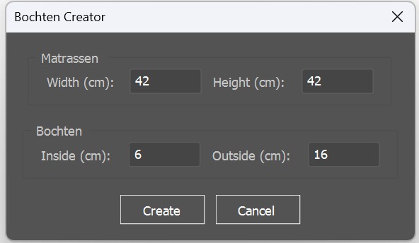
Bocht via the script menu
If the required bocht is not available in the library, we can create a mattress of this type, which will replace a standard bocht.
Following the same principle as creating a mattress through the script menu, we open the necessary panel. We enter the bocht data — width, height, and the sizes of the smaller and larger arcs.
We cut the krimps, create the contour, add the label, and don’t forget to create the second, mirrored part.
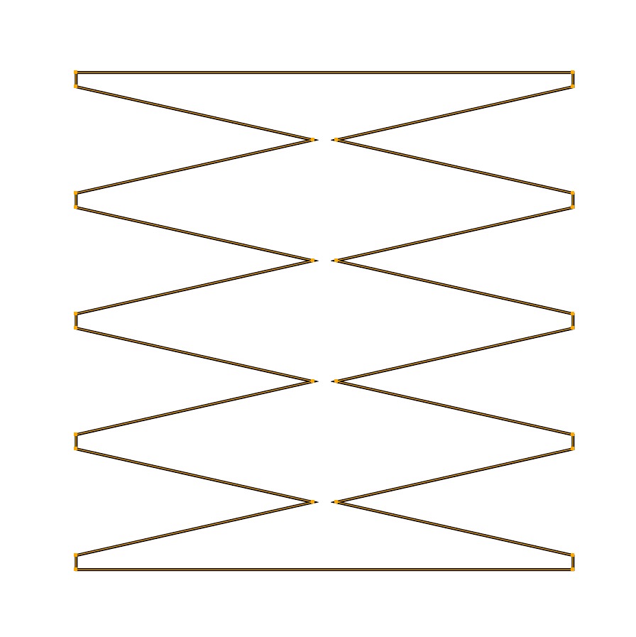
Creation based on the drawing in image «D-9.4»
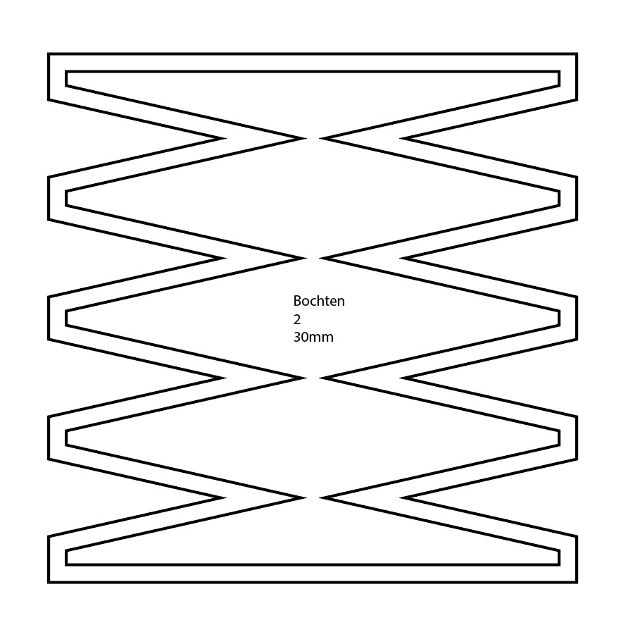
If the height is not specified in the drawing, then in the corresponding field we enter the same value as the width.
Keep in mind that this type of bocht is complete and does not require creating a mirrored version, unlike the bochts from the “bocht library.”
Additional dimensions
In the drawing «D-9.12» we see that an additional +4 cm has been added to the top part of the bocht.
We create a rectangle with the width indicated in the drawing under the calculated mattress width, and with a height equal to those +4 cm.
We merge the bocht with this rectangle by removing the line separating them, and then create the contour.

Image «D-9.12»

Image «D-9.13»

Image «D-9.14»
The “+4” label is shown for demonstration only. In real practice, you do not need to label such additions.
Inserts, cutouts, and krimps
Looking at the drawing «D-9.15», we see that we need to create a circular cutout. We create an ellipse with the required diameter. According to the drawing, we apply the offsets from the edges and from the top/bottom, remembering to add a split if necessary.
With DD, insert dimensions, or krimps, the situation is exactly the same. The measurement drawing specifies the locations, offsets, and dimensions of the required “additions”.

Image «D-9.15»

Image «D-9.16»

Image «D-9.17»
Keep in mind that in most measurement drawings, the bocht is shown as a “half” version.
Therefore, cutouts, splits, etc. that are shown “in the center” will actually be placed on the quarter;
2 krimps are only for one half — the full bocht has 4, just like a regular mattress.
The side of the quarter depends on the direction in which the bocht “faces” in the measurement drawing.
From drawing «D-9.15», we can determine that the split with the cutout is located on the lower right quarter, which is exactly how we illustrated it.
Zicht
If we see the label «zicht», it means that this bocht must be mirrored horizontally.
This does not refer to creating the second “mirror half,” but to the main bocht itself — after all additions and details have been applied — being flipped horizontally.

Image «D-9.18»
Download links
We can place the bocht library folder anywhere on the PC that is convenient for us.
Installing the script menu
Take the .jsx file and place it in the following directory:
C:/Program Files/Adobe/Adobe Illustrator (+ver)/Presets/en_US/Scripts


